Short answer
EV charging station design begins with vehicle energy demand and operating time. Convert those inputs into an AC and DC charger mix, site-power and load-management plan, safe bay and cable layout, accessible user path, network and payment workflow, climate strategy, service access and staged expansion. Qualified local professionals must approve the final electrical, civil and regulatory design.
A charger catalogue cannot decide the site. The same nominal power can produce different business results depending on vehicle voltage, dwell time, simultaneous demand, power sharing, charger availability, user access and the local grid boundary. Procurement should preserve these assumptions in one design brief so suppliers and contractors price the same outcome.
Translate vehicle demand into an operating requirement
For each vehicle group, record battery and connector information, expected energy on arrival, energy required before departure, arrival and departure distribution, days of operation and acceptable exceptions. For public or destination charging, estimate turnover and session energy rather than assuming every driver charges from empty to full.
| Application | Primary design input | Typical planning question |
|---|---|---|
| Apartment or workplace | Long dwell, user allocation and building demand. | How many vehicles must recover daily energy within a shared site limit? |
| Hotel or retail | Guest dwell, turnover, access and payment expectation. | Should many AC bays be combined with a smaller faster-charging option? |
| Fleet depot | Route energy, return waves, departure deadlines and reserve vehicles. | Which vehicles need priority, and how much power can be shifted across the dwell window? |
| Highway or public hub | Peak arrivals, queue tolerance, vehicle voltage and session duration. | How many connectors and what power-sharing behavior meet the service target? |
Choose an AC, DC or mixed architecture
AC charging uses the vehicle onboard charger, so the actual rate can be lower than the wallbox nameplate. It can be effective for longer parking windows and larger bay counts. DC charging supplies controlled DC power to the vehicle and can serve shorter dwell or higher energy demand, but usually brings a larger electrical, thermal, civil and service boundary.
For a mixed site, assign charger types by user need rather than prestige. Protect faster positions for vehicles that need them, and avoid using high-power equipment where the vehicle, site or operating window cannot benefit. Define whether power is fixed per connector or shared dynamically and what happens when multiple vehicles connect.
A worked example: energy first, charger rating second
Suppose a vehicle needs to add 40kWh to its battery before departure. Dividing that energy by the usable charging window gives the average battery-side power needed. This is an illustrative planning calculation, not a SUNFULL product test, a customer project or a guaranteed charging time.
| Illustrative requirement | Calculation | What the buyer still needs to check |
|---|---|---|
| One vehicle, 40kWh in 8 hours | 40kWh ÷ 8h = 5kW average into the battery. | Vehicle AC charging limit, usable parking time, charger settings and site-power allocation. A nameplate above 5kW alone does not prove the requirement will be met. |
| Four vehicles, each 40kWh in the same 8 hours | 160kWh ÷ 8h = 20kW average into all four batteries. | Overlapping arrivals, individual departure deadlines and allocation between vehicles. This is an energy average, not the required electrical service rating. |
| One vehicle, 40kWh in 1 hour | 40kWh ÷ 1h = 40kW average into the battery. | Vehicle DC charging curve, starting charge level, battery temperature, output range and power sharing. Do not assume a 60kW charger maintains 60kW throughout the session. |
Grid-side energy must also cover charging losses and auxiliary consumption. Connection time, queues, interruptions and battery charging limits can shorten the useful charging window or reduce delivered energy. Ask the project team to validate these assumptions before selecting equipment or sizing the electrical installation.
For background on why charging time varies with the battery, vehicle and equipment, see the U.S. Department of Energy charging equipment overview.
For longer-dwell options, compare the 7kW EV charger, 11kW EV charger and 22kW EV charger against the vehicle and supply conditions. For a shorter charging window, review the 60–180kW DC fast charger family with the same energy and departure requirements. Send your vehicle schedule and site-power information for a model-specific proposal.
Model the complete site-power path
Record the utility or facility point of connection, capacity available to charging, competing building loads, distribution equipment, cable routes and expansion allowance. If load management is proposed, identify the measurement source, update behavior, charger groups, priorities, fallback state and the party responsible for controls integration.
Solar and storage can support project goals, but generation, storage energy, storage power, conversion efficiency, grid rules and the charging profile must be modeled together. Do not subtract one solar nameplate value from one charger nameplate value and treat that as a finished design.
Design bays, cable reach and user access together
Map actual vehicle positions, charge-port locations, parking orientation and cable paths. Review mounting height, connector handling, cable weight, trip and drive-over risks, bollards, wheel stops, drainage, lighting, signage, pedestrian routes and maintenance clearances. Local accessibility requirements should be considered from the first layout, not added after equipment positions are frozen.
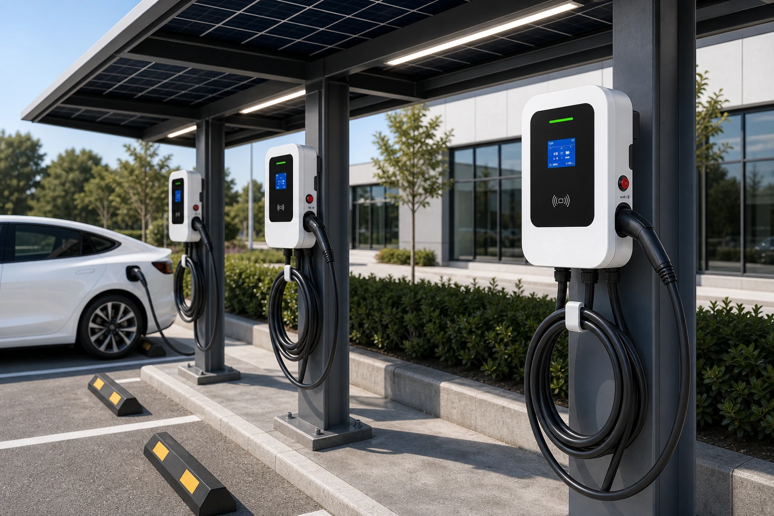
The charger image on a product page is representative of a product family; connector, screen, cable and mounting options depend on the selected model. Use controlled drawings for the quoted configuration before foundations, wall penetrations or cable routes are released for construction.
Account for climate, cooling and service access
Send the expected temperature range, direct sun, rain, flooding risk, dust, salt, humidity, altitude, ventilation conditions and impact exposure. Confirm the enclosure and cooling requirements for the selected model. Leave the clearances required to open doors, replace filters or cables, use lifting equipment where relevant and isolate the work area safely.
A site that blocks airflow or service doors can create operating problems even when the equipment specification is appropriate. Coordinate canopy, landscaping, fences, walls and adjacent bays with the model information and local safety plan.
Define network, OCPP, access and payment ownership
Map the journey from driver or employee to charger, local network, CSMS and payment service. Identify the target OCPP version, security profile, connectivity method, site router or cellular responsibility, RFID or app ownership, tariff authority, receipt or settlement need, session records, alarm routing, remote support and data policy.
Plan coverage and failover before installation. A cellular specification does not prove useful signal at a metal cabinet or underground car park. An Ethernet route does not exist until it is included in the site scope. Agree offline behavior and a commissioning test for the exact workflow.
Use load management as a defined control function
| Control question | Design decision | Acceptance evidence |
|---|---|---|
| What is the site limit? | Fixed allowance, dynamic building limit or another approved boundary. | Recorded source value and observed charger response. |
| How is power allocated? | Equal share, vehicle priority, departure time, charger group or operator rule. | Multi-vehicle scenario showing the intended allocation. |
| What happens after lost communication? | Safe fallback, local rule, recovery and alarm ownership. | Controlled interruption and return-to-service record. |
| Who can change settings? | Installer, operator, CSMS or controls provider role. | Access-control and configuration record. |
Reserve a realistic expansion path
Separate the opening phase from the ultimate site. Show future bays, charger types, simultaneous demand and expected operating changes. Review spare distribution capacity, transformer strategy, routes, foundations, network, controller or CSMS capacity, parking circulation and service space. The best early provision is project-specific; unused equipment is not automatically better than planned infrastructure.
Design brief and RFQ checklist
- Country, site type, climate and local project parties.
- Vehicle groups, connectors, energy demand, dwell windows and peak arrivals.
- Opening and future charger count, AC/DC mix and power-sharing expectation.
- Available site capacity, building demand interaction and load-management boundary.
- Parking drawing, bay dimensions, cable reach, mounting, accessibility and service access.
- Network coverage, OCPP or CSMS, RFID or app, payment and reporting workflow.
- Environmental, enclosure, cooling, impact-protection and maintenance conditions.
- Documents, pilot or sample, acceptance tests, quantity, branding and delivery schedule.
Request controlled drawings for the selected configuration
Available dimensions, installation information, manuals and applicable model-specific technical or compliance files can be reviewed after the equipment, options and destination are confirmed. Some controlled materials are shared privately with qualified project parties.
Prepare the sample, shipment and operating handover
Connect the equipment choice to a practical handover plan. Keep the agreed model and options consistent across evaluation, packing and installation records.
Evaluate the intended configuration
For a pilot or sample, agree the power, connector, cable arrangement, firmware and backend functions to be evaluated. Identify the test vehicles, available supply and responsible personnel, then record the results against those inputs. Use the pre-shipment FAT checklist to discuss applicable checks; a sample result should not be assumed to cover another configuration.
Match delivery to site readiness
Before dispatch, confirm package count, dimensions, gross and net weights, separately packed accessories and handling needs. Coordinate the receiving area and installation sequence with the local project team. For phased deliveries, reconcile each packing list with the order and track the remaining items separately. The installation planning guide helps connect shipment preparation with site responsibilities.
Keep a usable support record
At handover, retain the model, serial number, software version, configuration and agreed support contact. For a fault, share the displayed code, when it occurs and whether one or several vehicles are affected, without sending passwords or personal data. Use the maintenance and spare-parts guide to prepare the operating record and discuss the support scope in the order.
Official reference scope
These public sources support general site and accessibility planning. They do not certify SUNFULL or replace the local authority, utility, electrical, civil, accessibility, fire or building review.
- U.S. Access Board: accessible EV charging design recommendations
- Joint Office of Energy and Transportation: site design resources
- Joint Office of Energy and Transportation: industry alignment resources
Related product and planning pages
Buyer FAQ
What should be defined before selecting chargers for a commercial site?+
Define the vehicles, connectors, daily energy, dwell times, peak arrivals, user groups, available electrical capacity, parking layout, climate, network, payment or access workflow, operating hours, local project requirements and future expansion.
How do buyers decide between AC and DC charging?+
Compare the energy each vehicle must recover with the available parking time and site capacity. Long-dwell parking may suit managed AC charging, while shorter dwell or high daily energy can require DC. Many commercial sites use a planned mix.
Does SUNFULL provide the final site design and permits?+
SUNFULL can discuss equipment selection, system interfaces and available model-specific information. Qualified local professionals remain responsible for surveys, final electrical and civil design, utility coordination, permits, accessibility, fire and building requirements, installation and acceptance unless a written quotation states otherwise.
How should a site reserve for future expansion?+
Document later bay counts and power targets, then review spare electrical capacity, distribution space, cable routes, foundations, network coverage, controller capacity and parking geometry. Expansion provisions should be approved by the local project team.
Request an equipment path for your site brief
Send vehicle demand, dwell time, site capacity, parking plan, charger quantity, connector, software workflow, climate and future phase. We will identify configuration questions and available model-specific information.