Energy before power
Calculate the energy each vehicle must recover before departure, then model simultaneous demand instead of selecting chargers from maximum power alone.
Managed charging infrastructure for bus depots, logistics hubs and delivery fleets. Plan charger power, load management, RFID driver access, OCPP/CSMS reporting and maintenance before ordering hardware.
Fleet depot EV charging should start with vehicle count, battery size, daily mileage, return windows, departure priorities and available transformer capacity. Use AC where vehicles have long dwell time and DC for shorter turnaround or exception bays, then define load limits, connector rules, RFID identities and OCPP or CSMS reporting before selecting quantities.
Collect vehicle count, battery capacity, daily mileage, return state and route schedule.
Map arrival groups, departure times, priority vehicles and long-dwell versus fast-turnaround bays.
Confirm transformer size, spare capacity, input voltage, peak limit and expansion plan.
Define connector, bay layout, OCPP or CSMS, RFID user rules, reports, remote diagnostics and maintenance responsibility.
60kW to 120kW can fit overnight or moderate depot charging. 150kW to 180kW is useful when turnaround time is shorter.
OCPP/CSMS is strongly recommended for scheduling, reporting, remote diagnostics and driver or vehicle account control.
Send vehicle count, battery size, route schedule, depot grid capacity, connector standard, charger power and expected charging windows.

Fleet operators converting from diesel face a classic depot problem: if all vehicles charge at the same time, the grid connection and electricity bill become hard to control. They need chargers that match route schedules, driver access rules, available power, payment or cost-allocation policy and maintenance windows. For software scope, review the fleet charging management / CPO platform guide before confirming charger quantities.
| Planning item | What to confirm | Useful SUNFULL page |
|---|---|---|
| Depot layout | Bay count, cable route, vehicle turning radius, charger mounting, safety distance and service access. | Fleet charging solution |
| Power selection | AC for long-dwell vehicles, DC for top-up or tight turnaround, and future expansion space. | Power selection guide |
| Load management | Site power limit, transformer capacity, peak tariff, charging window and optional BESS buffer. | OCPP / CSMS platform |
| RFID/payment | Driver ID, employee charging, partner access, QR payment or POS terminal needs. | RFID, QR and POS guide |
| Maintenance | Remote fault alarm, spare cable/gun, module replacement, preventive inspection and service responsibility. | OCPP testing checklist |
Share fleet size, vehicle type, route window, daily mileage, parking time, available grid power, charger quantity, AC/DC mix, RFID or payment requirement, OCPP/CSMS backend preference and maintenance responsibility. This is more useful than asking for a charger price alone.
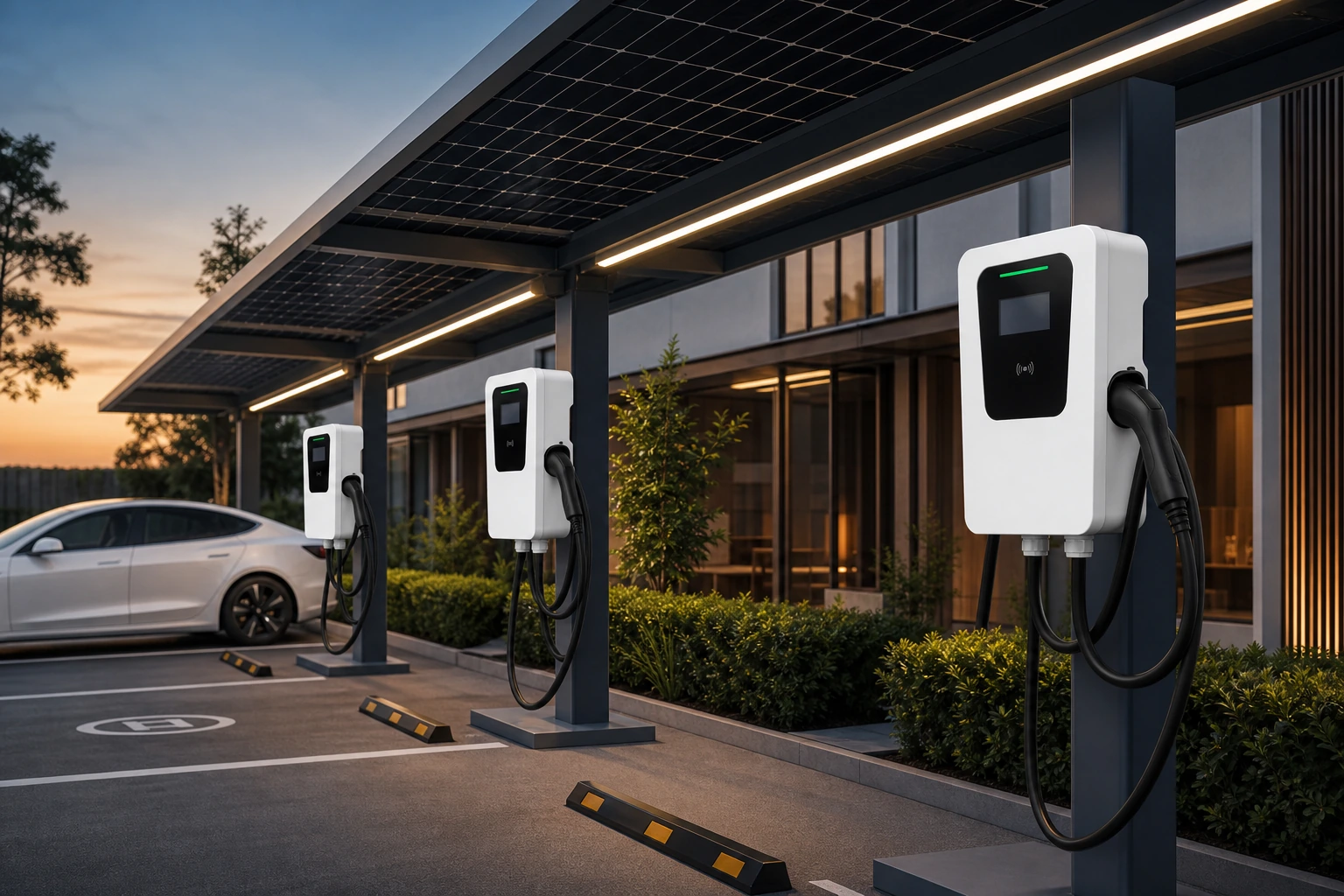
OCPP fleet management, RFID per driver
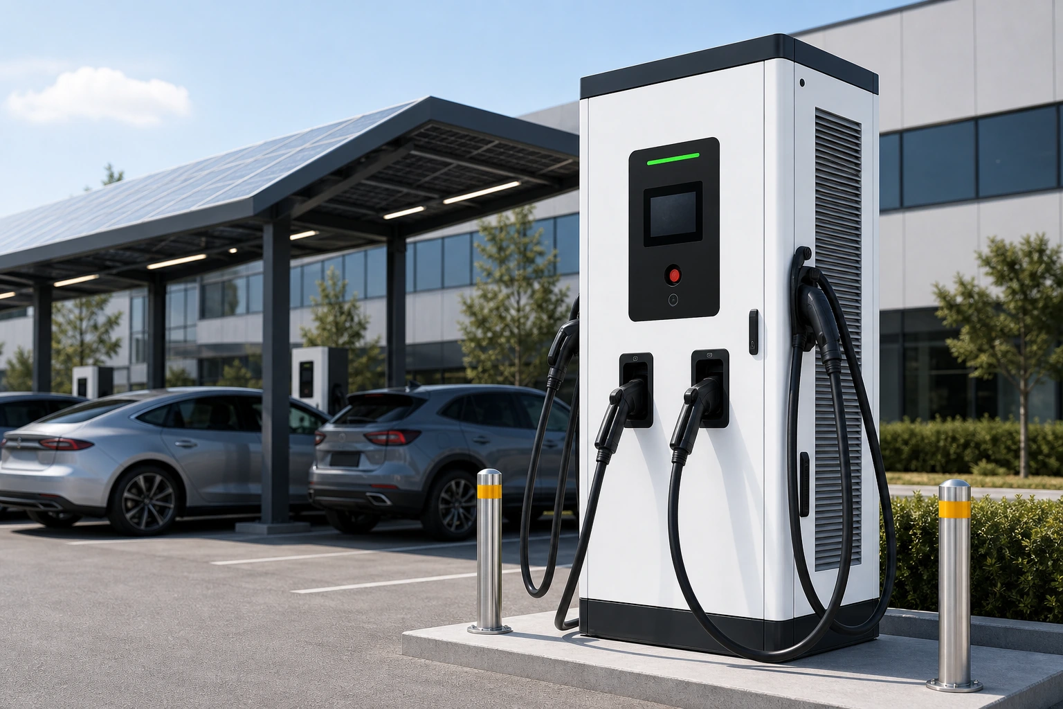
Top-up bays, 30min to 80%
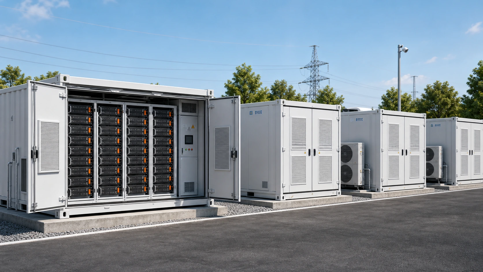
Peak shaving for large depots
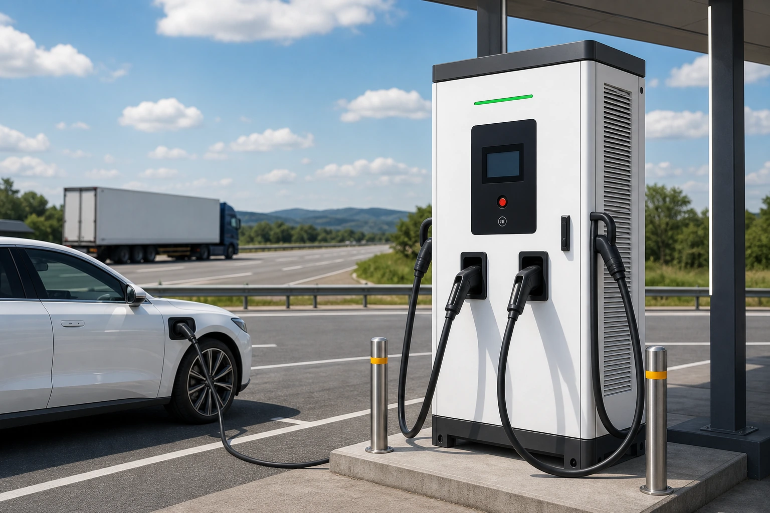
Higher-turnover depot and corridor charging
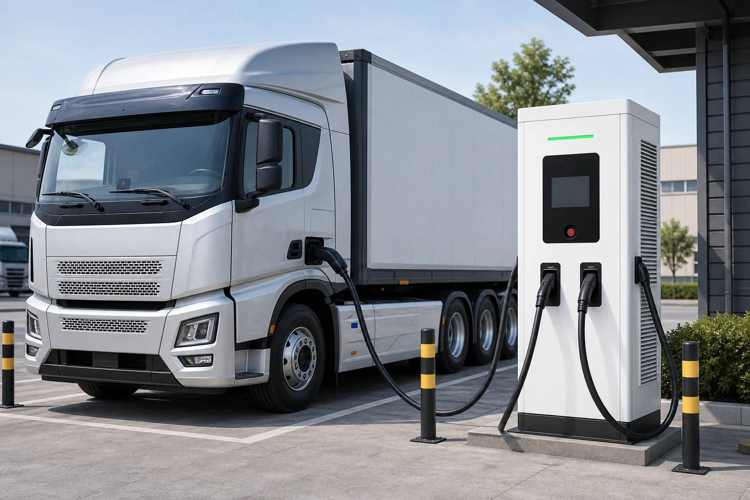
Route-window and dual-output planning for heavy fleets
A depot with 40 overnight bays may combine 22kW AC chargers for long-dwell vehicles with several DC top-up bays for exceptions. The design should limit simultaneous peak load, identify each driver or vehicle by RFID, and report kWh by session through the CSMS for cost allocation.
Start with available vehicle state-of-charge data, route schedules, charging windows and the depot power limit. Priority logic can then favor earlier departures or lower-charge vehicles, but readiness depends on data availability, vehicle demand, site capacity, charger uptime and the accepted CSMS control scope.
Yes. Each bay is configured with its own power limit and vehicle type. The scheduling algorithm treats each vehicle independently based on its actual energy need.
Designate 1-2 DC fast charger bays as on-demand bays. These are not part of the scheduled overnight program and can be used ad-hoc by drivers via RFID.
Third-party fleet-system integration must be defined and tested project by project. Provide the target platform, available API or webhook documentation, required data fields, authentication method and acceptance tests before the charger, CSMS and integration responsibilities are agreed.
Private depots usually use RFID driver or vehicle ID instead of POS payment. If chargers will be opened to public users, contractors or partner fleets, QR payment, app payment or POS terminal scope should be confirmed before ordering.
Send us your site plan or power requirements and the team can review the project scope and confirm the next technical and commercial steps.
Get Free System DesignUse these pages together to define protocol version, backend, authentication, payment, load management and acceptance testing before ordering chargers.
Compare OCPP 1.6J, OCPP 2.0.1, cloud operation and integration scope.
Choose protocol scope by backend functions and lifecycle requirements.
Verify connection, meter values, remote commands, alarms and firmware.
Plan charging windows, transformer capacity, priority and managed load.
Review a commercial fleet charger platform before fixing the depot power plan.
Define authorization, tariff and settlement workflows before integration.
EV fleet charging should be sized from route energy, return times, dwell windows, reserve vehicles and site capacity. Effective EV fleet charging solutions connect those operating inputs to charger quantity, power sharing, bay layout, CSMS rules and a phased expansion path.
Calculate the energy each vehicle must recover before departure, then model simultaneous demand instead of selecting chargers from maximum power alone.
Set vehicle priorities, charging windows and exception rules so the control plan supports operations when several vehicles return together.
Reserve electrical, civil, network and parking provisions for later bays so the EV fleet charging infrastructure can grow without repeating avoidable site work.